


Views: 0 Author: Site Editor Publish Time: 2026-09-23 Origin: Site


Procuring industrial HVAC systems involves extremely high stakes for modern facility managers. Undersize the equipment, and you leave workers sweltering while causing vital machinery to overheat and fail prematurely. Oversize the system, and you waste precious capital while pumping excess, damaging humidity into the building. Finding the perfect balance demands a rigorous, math-driven framework for industrial evaporative air cooler sizing based strictly on volumetric airflow.
We built this comprehensive guide to give you the exact engineering formulas needed to evaluate airflow capacity in cubic meters per hour (m³/h) or cubic feet per minute (CFM). You will learn how to accurately calculate your facility's requirements step-by-step. We will explore the precise environmental variables you must factor in, including Air Changes per Hour (ACH), local wet-bulb temperatures, and exhaust pathways. By the end, you will confidently specify the optimal system for your operation.
Facility managers often struggle when they need to evaluate conflicting vendor quotes. Standardizing your approach solves this frustrating problem entirely. You need a reliable, standardized mathematical baseline to cross-check equipment specifications objectively. We rely on a proven engineering formula to determine the exact volumetric airflow required for any industrial space. This removes all guesswork from your procurement cycle.
The baseline calculation relies on three main variables. For metric environments, you calculate the required Airflow (m³/h) by multiplying the Area (m²) by the Ceiling Height (m) and then multiplying that result by the Air Changes per Hour (ACH). If you use imperial units in your region, the formula adapts slightly. You find the required Airflow (CFM) by multiplying the Area (sq ft) by the Ceiling Height (ft) and by the ACH, then dividing the entire total by 60.
Defining these variables correctly ensures accurate results. One common mistake involves using the total roof peak height in the calculation. Instead, you should always calculate the "effective volume." For most ambient space cooling purposes in unstratified facilities, you only need to cool the lowest 3 to 4 meters. This represents the occupied zone where workers and heat-generating machines operate. Cooling the empty air space above 4 meters wastes massive amounts of energy and artificially inflates your equipment costs.
You must establish a strong trust factor when reviewing data sheets. Note that manufacturer capacity ratings are usually tested under ideal, zero static pressure conditions in a laboratory. Real-world applications never match these perfect scenarios. Ducting layouts, directional louvers, bends in the airpath, and wetted filter pads all create significant airflow resistance. Practical sizing should always include a 10-15% safety margin to compensate for this ducting and filter resistance. This margin guarantees your equipment actually delivers the promised cooling effect directly on the factory floor.
Calculating the correct ACH forms the essential foundation of proper system design. You must classify your facility's specific heat generation carefully to select the correct ACH multiplier. High-heat machinery demands significantly more air replacement than a quiet storage warehouse. This evaluation criteria prevents both inadequate cooling and unnecessary equipment expenditures.
We categorize facilities into three primary baselines based on their operational intensity. Each category reflects a different thermal environment.
Table 1: ACH Recommendations by Facility Heat Load
| Heat Load Category | Facility Types | Recommended ACH |
|---|---|---|
| Low Heat Load | Warehouses, Assembly Lines, Logistics Centers | 20–25 ACH |
| Medium Heat Load | Fabrication Shops, Commercial Kitchens, Light Manufacturing | 30–40 ACH |
| High Heat Load | Foundries, Glass Plants, Engine Rooms, Injection Molding | 40–50+ ACH |
Understanding sensible versus latent heat adds another vital layer to this evaluation. Machinery, uninsulated steam pipes, and high-density personnel add massive amounts of sensible heat to the environment. This sensible heat raises the dry-bulb temperature quickly. You need higher airflow velocities to combat this thermal buildup. Fast-moving air evaporates sweat off human skin, creating a distinct physiological cooling or "wind-chill" effect. Proper ACH ensures this air moves fast enough to maintain worker comfort, even if the absolute room temperature remains slightly warm.
Deciding between blanketing the entire building or targeting specific workstations determines your overall project scope. Both solution categories have distinct advantages and specific engineering requirements. You must align the chosen method with your daily operational layout.
Whole-facility cooling works best for dense production floors. It excels when heat distributes uniformly across the space, such as in an active garment factory or a large machining hall. This approach requires larger upfront capital because you will need multiple synchronized units. It also requires extensive roof or wall penetrations for ducting. However, it creates a perfectly consistent temperature profile throughout the entire building, maximizing flexibility if you ever move machinery.
Spot cooling, also known as zonal or targeted cooling, offers an highly efficient alternative for expansive layouts. It suits large distribution centers perfectly. In these massive buildings, actively occupied floor space often represents only 10% of the total area. Cooling the empty storage racks makes absolutely no sense. For spot cooling, your calculations shift away from total room volume. Instead, you focus heavily on achieving a specific air velocity at the worker level, usually delivered through localized drop ducts.
We must highlight a critical implementation risk here. Pumping localized cool air into a highly enclosed space introduces serious issues. Spot cooling in a highly enclosed space without adequate exhaust will simply raise local relative humidity. By the end of a shift, worker comfort decreases dramatically as the air becomes saturated. The environment feels sticky, oppressive, and uncomfortable. You must pair spot coolers with proper ventilation to prevent this outcome.
Evaluating standard equipment capacities against your specific facility needs requires clear, deductive logic. Many engineers shortlist equipment based on modular efficiency. Let us break down the exact math for one of the most widely used machine sizes in the industry.
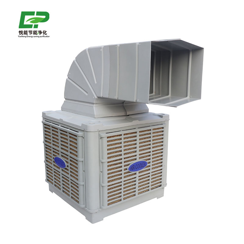
Consider specifying a standard 18,000 m³/h evaporative air cooler. Imagine deploying it in a facility section measuring 150 square meters. The effective ceiling height stands at 4 meters. The total volume equals 600 cubic meters (150 m² × 4 m). When you divide the 18,000 m³/h capacity by this 600 m³ volume, you get exactly 30 Air Changes per Hour (18,000 / 600 = 30). This hits the exact sweet spot for a medium heat load facility.
This specific capacity adapts beautifully to various deployment scenarios. You can position these units perfectly over active loading docks. They serve localized assembly zones brilliantly. In a massive 1,000 square meter warehouse, deploying six to seven modular units creates an incredibly resilient, distributed cooling network.
Scalability makes this modular approach superior to centralized systems. Installing multiple mid-sized units provides significant maintenance and redundancy advantages. If one unit requires routine servicing, the others continue cooling the plant uninterrupted. Conversely, a single massive custom 100,000 m³/h central unit represents a single point of failure. Furthermore, standardized equipment reduces the structural load on your roof compared to lifting one giant air handler into place.
Expertise and transparency matter in HVAC design. Evaporative cooling is not mechanical air conditioning. It operates on entirely different thermodynamic principles. The technology is strictly bound by local psychrometric conditions. You must understand these climate limitations to avoid catastrophic system failure.
The wet-bulb temperature dictates your maximum theoretical temperature drop. Ambient humidity acts as a strict barrier to performance. As relative humidity increases, the water evaporation rate decreases. High airflow simply cannot overcome a high wet-bulb temperature. If the outside air is already heavily saturated with moisture, the cooling pads cannot absorb more water. You will merely circulate warm, damp air throughout the factory.
Compliance and asset protection depend entirely on this climate check. We strongly warn against undersizing airflow in humid climates. Doing so restricts air movement drastically. Slow, highly humid air leads directly to condensation on cold surfaces. This moisture settles on expensive metal inventory and finished goods. It can cause severe rust and corrosion on precision CNC machinery. You must push enough air volume at high velocities to prevent moisture from settling. Always consult a local psychrometric chart before finalizing your design specs.
The most common point of failure in industrial evaporative cooling happens during exhaust planning. Ignoring air exhaust guarantees poor performance. You can specify the highest quality equipment available, but it will fail completely without a calculated exit path.
Evaporative systems operate heavily on the "Open Door" principle. They process 100% fresh outside air. For every 18,000 cubic meters of air pumped into a facility, exactly 18,000 cubic meters must exit. If the air gets trapped, positive pressure builds up inside the room. This internal pressure eventually matches the fan's output pressure, neutralizing the system and stopping the cooling process entirely.
You have two primary options for air displacement. Each requires distinct architectural calculations.
Balancing the input and output airflow ensures optimal static pressure. It keeps the cooling breeze flowing steadily and efficiently across the production floor throughout the entire work shift.
Designing an effective industrial cooling system requires strict adherence to mathematical reality and environmental data. Your decision-making framework should always follow four sequential steps: calculate the effective Volume, determine the necessary ACH based on heat load, perform a Climate Check against local wet-bulb temperatures, and finalize your Exhaust Planning. Skipping any of these steps compromises the entire installation.
We strongly advise buyers to look past flat "square footage" marketing claims. Demand actual psychrometric charts from your vendors. Ask them for static pressure drop data to prove their equipment will perform under real-world ducting resistance. Do not guess when engineering your plant's environment. Consult with a qualified application engineer specializing in industrial evaporative air cooler sizing to review your facility blueprints. They can map out the exact airflow distribution and recommend the most efficient ducting strategy for your specific layout.
A: Undersizing results in insufficient air velocity to create a cooling effect and allows internal heat and humidity to build up, often making the space feel hotter than it would with no cooling at all.
A: Yes. To convert m³/h to CFM, divide the m³/h value by 1.699. An 18,000 m³/h cooler is equivalent to roughly 10,600 CFM.
A: For localized spot cooling via ductwork, ceiling height is less critical because the calculation focuses on target velocity at the workstation. However, for ambient space cooling, ceiling height directly dictates the total air volume to be displaced.
A: Depending on the heat load and a standard ceiling height of 3 to 4 meters, it effectively cools between 100 and 150 square meters (approximately 1,000 to 1,600 square feet).


