


Views: 0 Author: Site Editor Publish Time: 2026-09-14 Origin: Site


Accepting delivery of industrial ventilation equipment shifts the liability directly from the manufacturer to your facility. You become fully responsible for its safe operation the moment it hits your loading dock. Because Fiberglass Reinforced Plastic (FRP) is specifically deployed for highly corrosive, high-stakes environments, you cannot afford any passive assumptions. Structural flaws or mismatched specifications can quickly lead to catastrophic operational downtime and severe safety hazards.
This guide provides a rigid, evidence-based framework for inspecting your equipment prior to final sign-off. We will help you ensure the physical unit strictly matches your engineering requirements and industry compliance standards. You will learn exactly what to evaluate, from external casing integrity to internal mechanical clearances. We designed this inspection protocol to protect your facility from installing compromised or incorrect equipment. Treat this acceptance phase seriously, and you will secure long-term reliability for your ventilation system.
Discrepancies between purchased specifications and delivered equipment create massive business problems. These errors often result in costly compliance failures. Hazardous environments compound this risk significantly. You cannot install an underperforming unit in a facility handling toxic chemical fumes. Delivering the wrong motor rating or an incorrect impeller profile disrupts project timelines. You must catch these discrepancies while the unit still sits on the shipping pallet.
Document reconciliation acts as your first line of defense. Start by locating the manufacturer nameplate on the equipment housing. Read it carefully. Match this physical nameplate directly to your approved purchase order. Verify the total airflow capacity, measured in cubic feet per minute (CFM). Check the designed static pressure rating. Confirm the motor horsepower (HP) and the rotational speed (RPM). Even a slight deviation in RPM drastically alters the aerodynamic performance. If any number looks wrong, flag the delivery immediately.
Compliance validation requires rigorous attention from your engineering team. If your exhaust fan is designated for volatile environments, check the motor certifications carefully. You must verify ATEX or explosion-proof ratings. Check the motor tags for specific Class and Division ratings. Ensure they meet the exact volatility classification of your facility zone. Standard duty motors will ignite explosive fumes. Never compromise on these electrical certifications.
Supplier accountability separates good vendors from risky ones. Demand baseline vibration documents before taking physical possession. Request the comprehensive Factory Acceptance Test (FAT) reports. A reliable manufacturer tests every single unit before crating it for shipment. You need this factory data to establish your operational baselines. If a vendor refuses to provide FAT documentation, consider it a major red flag.
Table: Essential Document Reconciliation Checklist
| Component to Verify | Target Metric | Why It Matters | Failure Consequence |
|---|---|---|---|
| Motor Nameplate | Horsepower (HP) & RPM | Dictates power consumption and speed. | Overheating or insufficient draft. |
| Housing Tag | CFM & Static Pressure | Ensures proper air volume movement. | Inability to clear toxic fumes. |
| Certification Label | ATEX / Ex-Proof Class | Validates safety in volatile zones. | High risk of spark ignition. |
| FAT Report | Vibration Velocity (in/s) | Confirms factory dynamic balance. | Premature bearing destruction. |
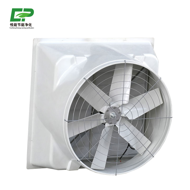
Fiberglass Reinforced Plastic consists of multiple engineered layers. Manufacturers build it to withstand severe chemical attacks over many decades. However, material realities dictate that the hand-layup or winding process is prone to human error. Flaws in the manufacturing process directly impact chemical resistance. They also destroy structural integrity. Poor resin application leaves the underlying glass fibers highly vulnerable to acid vapor degradation.
Surface evaluation demands bright lighting and keen eyes. Instruct your team to inspect the inner and outer casing thoroughly. Look closely for air bubbles, commonly known as voids. Search for any delamination between the thick fiberglass layers. Identify dry spots where the liquid resin failed to saturate the glass fibers. Watch out for spider cracking along high-stress curves and transition points. The interior corrosion barrier demands extra scrutiny. It must remain perfectly smooth and continuous. Rough internal patches will trap corrosive liquid agents.
Flange and mounting integrity ensure safe ductwork connections. Flanges connect the main ventilation unit to your facility ductwork system. Check flange flatness using an industrial straightedge tool. Verify exact bolt-hole alignment across the entire circumference. Un-machined or uneven flanges create severe stress fractures during final installation. When your technicians tighten bolts over an uneven FRP surface, the rigid material bends and snaps.
The impeller acts as the functional heart of your entire system. It moves the aggressive air and dictates ultimate performance outcomes. Impeller imbalance creates violent mechanical vibrations. These vibrations travel through the shaft and cause premature bearing failure. They also trigger massive structural fatigue across the fiberglass housing. You must verify mechanical integrity before applying any electrical power.
Gap measurement requires high precision tools. Detail the necessity of checking the clearance between the impeller tips and the surrounding housing. Use long brass feeler gauges for this exact task. Too tight of a gap risks dangerous friction sparks. Sparks trigger catastrophic fires in explosive chemical environments. Conversely, too loose of a gap allows massive air bypass. This bypass heavily compromises aerodynamic efficiency and lowers total CFM output.
Shaft and hardware checks prevent immediate startup failures. Assess the main drive shaft for perfect straightness. Use a dial indicator to measure shaft runout. Inspect the keyway security closely at the central impeller hub. Examine the physical seating of all pillow block bearings. They must sit completely flush against their steel mounting pedestals. Any gap under the bearing foot indicates a warped base.
Specific model verification requires checking heavier components. For heavy-duty configurations, such as a model 1060 frp industrial exhaust fan, you must exercise extra caution. Verify that the heavier impeller mass is properly supported by reinforced structural steel. Ensure it is statically and dynamically balanced according to ISO 1940-1 standard requirements. Request the specific balance grade certificate from the factory. Grade G6.3 is standard, but Grade G2.5 provides superior longevity.
Chart: Baseline Mechanical Clearances Matrix
| Measurement Area | Standard Tolerance Range | Inspection Tool Required |
|---|---|---|
| Impeller Tip Clearance | 1% of wheel diameter (approx.) | Extended Feeler Gauges |
| Drive Shaft Runout | Less than 0.002 inches | Magnetic Base Dial Indicator |
| Bearing Base Flatness | Zero visible gap | Precision Straightedge |
| Belt Deflection | 1/64 inch per inch of span | Belt Tension Gauge |
Assess the fan for true integration readiness. Never assume factory electrical settings remain perfect after thousands of miles of transit. Shipping vibrations frequently loosen tight electrical connections and shift mechanical drives. Prepare the unit for site electrical integration methodically. Protect your electrical technicians by verifying the integrity of all mounted components first.
Belt and drive inspection applies to indirectly driven setups. For belt-driven units, instruct your team on checking sheave alignment. Use a precision laser alignment tool rather than a simple string. Check the initial belt tension. We know belts stretch during operation. Note that you will need a scheduled readjustment after the first 24-hour break-in period. Loose belts cause slippage and generate severe friction heat.
Motor housing inspections prevent weather damage. Inspect the motor weather covers thoroughly. Ensure they sit tightly without rattling. Test the mounting rigidity of the motor slide base. Look closely at the motor condensation drains. Ensure they point directly downward based on your final installation angle. Water must drain freely away from the internal copper windings to prevent short circuits.
Grounding mechanisms prevent dangerous static discharge events. Verify the presence of anti-static grounding cables. This is highly critical. FRP materials naturally build up high levels of static charge from air friction. You must verify the integrity of all grounding lugs. The carbon-impregnated anti-static layers within the fiberglass must connect to an earth ground. Use a certified megohmmeter to verify electrical continuity across the entire casing profile.
Moving from passive inspection to active testing introduces serious implementation risk. You must follow strict engineering protocols to avoid voiding your warranties. Never rush the startup sequence. Hasty electrical connections often result in backwards rotation. Backwards rotation damages the aerodynamic profile of the impeller blades. Take deliberate steps to safely transition the equipment into active duty.
Prepare carefully for your dry run preparation. Outline the "bump test" procedure for your field technicians. You briefly energize the motor to verify correct rotational direction. Do this without connecting the unit to the main ductwork system. An un-ducted ventilation system behaves entirely differently than a ducted one. It pulls more amperage when unrestricted. Keep the bump test run time incredibly short, typically under ten seconds.
Establishing baselines guarantees long-term tracking accuracy. Advise your team to take initial amp draw readings during the bump test. Record detailed vibration signatures during this Site Acceptance Test (SAT). Compare your new field readings against the original factory records. Large deviations indicate hidden transit damage or poor foundation installation. You must document these baselines before normal production begins.
Provide a clear decision framework based on the inspection findings. Do not leave the final acceptance up to interpretation. Follow this strict logic path:
A rigorous inspection protocol safely bridges the gap between theoretical engineering specifications and harsh operational reality. By thoroughly evaluating the casing, checking mechanical clearances, and verifying electrical readiness, you mitigate the heavy risk of early equipment failure. Proper inspection ensures your investment performs exactly as designed in corrosive environments.
Treat this acceptance inspection not as a bureaucratic formality, but as the foundational first step of your preventive maintenance program. The data you gather today establishes the baseline for years of future troubleshooting. Document all findings meticulously. Take detailed photographs of any discrepancies. Ensure you finalize this documentation before the installation crew leaves the site.
A: Look for visible defects like dry spots, exposed whitish glass fibers, and uneven resin coats. You might also see air bubbles trapped beneath the surface layer or fine spider-web cracking along the flanges. A properly manufactured unit features a perfectly smooth, continuous interior corrosion barrier without rough patches.
A: Dynamic balancing must be completed at the factory using specialized equipment before shipping. However, you must verify this balance on-site during commissioning. Technicians take vibration readings during the site acceptance test to ensure the impeller remained balanced throughout the transit and installation process.
A: Standard industry guidelines suggest a clearance of roughly 1% of the wheel diameter. However, tolerances vary significantly by design. You must consult the specific manufacturer's manual. The gap must be wide enough to prevent friction sparks, yet tight enough to maintain aerodynamic efficiency and prevent air bypass.


