


Views: 112 Author: Site Editor Publish Time: 2026-10-21 Origin: Site


Choosing the right exhaust fan for a workshop is not something you want to guess. A fan that is too small may leave heat, fumes, and stale air inside the building. A fan that is much larger than needed can add noise and use more power than necessary. The goal is pretty simple: move enough air for the space without making the ventilation system harder to run.
Most fan sizing starts with Cubic Feet per Minute, or CFM. This tells you how much air the fan can move in one minute. But CFM is only the starting point. Room size, workshop activity, ducts, filters, louvers, and fresh-air openings can all change the result.
This guide walks through the main calculations and the practical details that matter when choosing an industrial exhaust fan. The math is not especially difficult. The important part is using realistic numbers from the actual workshop instead of relying only on the airflow number printed in a catalog.
Start with the workshop volume and a suitable Air Changes per Hour (ACH) target to estimate the required CFM.
A fan's advertised free-air CFM may be higher than the airflow it delivers after ducts, filters, louvers, and other restrictions are added.
Exhaust air needs a way to be replaced. Without enough incoming air, the ventilation system may not move air as expected.
Drive type, motor, mounting position, noise, and maintenance should be considered along with airflow.
A good place to begin is the airflow calculation. It gives you a reasonable starting point before comparing individual fan models. For basic industrial exhaust fan sizing, the common formula is:
Volume (Length × Width × Height) × Air Changes per Hour (ACH) ÷ 60 = Target CFM
First, work out how much air is actually inside the room. For a simple rectangular workshop, that means multiplying the length, width, and height. Buildings with sloped roofs or unusual layouts may need a slightly closer look.
Measure the length and width of the workshop.
Use a realistic average ceiling height. A pitched roof should not automatically be calculated from its highest point.
For spaces filled with very large permanent equipment, consider whether that equipment noticeably reduces the open air volume.
Here is an easy example. Say a machine shop is 50 feet long, 40 feet wide, and 15 feet high. Its volume is 30,000 cubic feet. If the selected ventilation target is 10 ACH, the calculation is 30,000 × 10 ÷ 60. That gives a starting airflow target of 5,000 CFM.
One thing people sometimes miss is when the workshop actually needs the most ventilation. A quiet morning shift and a busy production period may create very different amounts of heat, dust, or fumes. It makes more sense to size around normal peak operating conditions than around an almost empty building.
Not every workshop needs the same amount of air movement. A storage building has very different ventilation needs from a welding area or repair garage. Air Changes per Hour, usually shortened to ACH, gives you a simple way to compare those needs.
ACH describes how many times the room's air volume is replaced in one hour. A higher number means faster air exchange. The right range depends on what happens inside the building and what kind of contaminants or heat the ventilation system needs to handle.
Light Assembly / Warehousing: These spaces often need less air exchange because there are fewer fumes and airborne particles. Ventilation is usually focused on general heat and humidity control.
Machining / Automotive Repair: These areas may need more airflow because of oil mist, vehicle exhaust, heat, and light process fumes.
Welding / Woodworking / Paint: These jobs can release much more dust, smoke, or vapor. General room ventilation may also need to work together with local extraction equipment near the source.
ACH ranges are useful for early planning, but they should not be treated as the only design rule. Local codes, the material being handled, process emissions, and exposure requirements can change the ventilation target. If several processes take place in one workshop, the higher-demand areas deserve extra attention when choosing a workshop ventilation fan.
Table Title: Recommended ACH Guidelines by Application Severity
Facility Type / Activity | Typical ACH Range | Main Ventilation Concern |
|---|---|---|
Warehousing & Storage | 4 - 6 | Heat and humidity |
Machine Shops | 10 - 15 | Coolant mist, heat, and process fumes |
Auto Repair Garages | 12 - 18 | Vehicle exhaust and chemical vapors |
Commercial Paint Areas | 25 - 35 | Paint mist and solvent vapors |
Welding & Fabrication | 20 - 30 | Welding fumes, smoke, and fine particles |
The airflow number in a fan catalog does not always tell the whole story. Some ratings are measured with very little resistance around the fan. A real workshop may have ducts, filters, dampers, screens, or weather covers. Each one makes it a little harder for air to move.
That resistance is called static pressure. As static pressure goes up, the actual exhaust fan airflow can go down. This is one reason two fans with similar catalog CFM numbers may perform differently after installation.
Look around the planned airflow path and note anything that may add resistance. Common examples include:
Long sections of ductwork.
Sharp bends and 90-degree elbows.
Weather hoods and rain covers.
Backdraft dampers and louvers.
Air filters that become more restrictive as they collect dust.
Static pressure is commonly shown in inches of water gauge, written as in. w.g. The useful document here is the fan performance curve. Instead of showing only one maximum airflow number, the curve shows how much air the fan can move at different pressure levels.
For example, imagine the system needs 5,000 CFM and the expected resistance is 0.25 in. w.g. Look for the point on the fan curve where those two values meet. If the fan reaches 5,000 CFM only with no resistance, it may not be the right choice once it is connected to the real system.
Filters also change over time. A clean filter allows air through more easily than a dirty one. Leaving a little practical capacity for normal filter loading can help the system stay closer to its target airflow between maintenance visits.
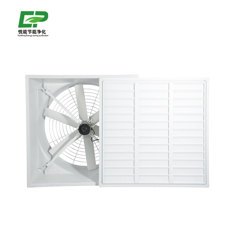
An exhaust fan removes air from a building, but that air has to come from somewhere. If there is not enough incoming air, the building starts operating under stronger negative pressure. At that point, even a large fan may move less air than expected.
That is why negative pressure ventilation should be planned together with makeup air. The exhaust side and intake side are really two parts of the same system.
Too much negative pressure can create several practical problems:
Doors may become harder to open or may close more quickly than expected.
Air may rush through cracks and small openings instead of entering through the planned intake points.
Combustion appliances can be affected if the building pressure is not properly managed.
The exhaust fan may deliver less airflow because it is working against additional pressure.
A practical design gives incoming air a clear path. Larger intake openings keep the incoming air velocity lower and usually make the room more comfortable. Passive louvers are common in many workshops, while larger facilities may use powered makeup-air equipment.
A common starting point is to provide more free intake area than exhaust opening area. The exact amount depends on the louver design, fan airflow, building pressure target, and other restrictions. If doors are difficult to open or the fan seems weaker after the building is closed up, the intake side is one of the first things worth checking.
Once the airflow requirement looks reasonable, you can start comparing actual fan designs. Good industrial fan selection is not only about picking the highest CFM. The drive system, motor, mounting method, noise, and maintenance can matter just as much after a few years of use.
Start with the drive type. Direct-drive fans connect the motor more directly to the fan assembly and do not use a belt. With fewer belt-related parts to inspect or replace, the setup can be fairly straightforward to maintain.
Belt-drive fans use belts and pulleys between the motor and fan. The pulley arrangement can provide more flexibility when adjusting fan speed. The motor position may also be separated from the main airflow path in some designs, which can be useful for certain workshop conditions.
Chart Title: Direct Drive vs Belt Drive Comparison Chart
Drive Feature | Direct Drive Fans | Belt Drive Fans |
|---|---|---|
Maintenance | No drive belts to inspect or replace | Belts need periodic inspection and tension checks |
Speed Adjustment | Depends on motor and control setup | Pulley changes can provide additional adjustment options |
Motor Arrangement | Commonly integrated closely with the fan assembly | Can allow more separation between the motor and fan section |
Typical Reason to Choose | Simple layout and reduced belt maintenance | Service flexibility and adjustable drive arrangements |
Belt-drive fans are often chosen when buyers want more room to adjust the drive setup later. Changing pulley sizes can alter fan speed, and the motor can sometimes sit farther away from the main airflow. That can be useful in workshops where heat, dust, or moisture are part of the daily environment.
The motor itself is worth checking before the fan is ordered. Start with the power supply already available in the building. Smaller workshops may use single-phase power, while larger plants often have three-phase power. There is no reason to make this part complicated. The motor just needs to match the electrical system and the way the fan will actually be used.
The surrounding conditions matter too. A motor in a dry storage building does not face the same conditions as one installed near dust, moisture, or process heat. TEFC motors are commonly used where extra protection from the surrounding environment is helpful. If flammable vapor, gas, or combustible dust is present, standard equipment may not be suitable. That kind of site needs equipment selected for the actual hazardous area classification.
Fan location is another thing that can change the result more than people expect. A wall fan usually works best when fresh air can enter from another part of the building and travel across the work area. Roof fans are useful when most of the unwanted heat collects overhead. There is no universal mounting position. It depends on where the heat or fumes start and where fresh air is coming in.
Then there are the small practical details. They are easy to overlook when everyone is focused on CFM. Is there enough room to clean the fan? Can someone reach the motor or belt without taking apart the whole frame? Is the fan right beside a workstation where the noise could become annoying after eight hours? These details seem minor on a drawing, but they become very noticeable after installation.
Fan sizing does not need to start with a long list of product models. Start with the room. Work out its volume and get a reasonable idea of how often the air needs to be changed. That gives you the first CFM number to work with.
After that, look at what is between the fan and open air. A short wall opening is very different from a system with filters, dampers, and several meters of duct. Those parts add resistance, and the fan has to deal with it.
The intake side is just as easy to miss. If a fan keeps pushing air out but fresh air has no clear way back in, performance can drop. Sometimes the problem is not the exhaust fan at all. The building simply needs a better path for replacement air.
Once those points make sense, comparing fans becomes much simpler. Check the motor, drive type, mounting space, noise, and access for maintenance. A basic workshop may only need a straightforward wall-mounted setup. More complicated spaces, especially those with hazardous materials or long duct runs, deserve a closer engineering review.
A: You could, but it may create a new set of problems. More airflow often means more noise, and it can remove heated or cooled indoor air faster than needed. If the building does not have enough intake area, the larger fan may also struggle to get the airflow you expected. A little extra capacity can be useful, but going much bigger is not automatically safer.
A: A manometer is normally used for this. The harder part is choosing the right place to take the reading. A measurement taken at the wrong point in the duct may not tell you much about what the fan is actually dealing with. For a simple system, this may be easy enough to check. With longer duct runs or several branches, it is usually better to have someone familiar with ventilation testing do it.
A: Think about the route you want the air to take. If fresh air enters through a door or louver on one side of the workshop, putting the exhaust fan farther away can help pull that air across more of the room. A higher mounting position can make sense when heat gathers near the roof. What you want to avoid is placing the intake and exhaust so close together that the fresh air leaves before it reaches the work area.


